There are three main types of electrical outputs for pressure sensors: millivolts (mV), volts (V), and current (mA).
It is important for engineers to understand which sensor is suitable for their application to ensure the correct selection.
Next, the advantages, disadvantages, and wiring of millivolt, volt, and current output pressure sensors are described.
1. Millivolt output pressure sensor
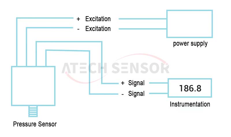
Pressure sensors with millivolt outputs are often used in laboratory applications. The main characteristics are low cost, small size, and the need for a regulated power supply. The level of the millivolt signal is very low, limited to short distances (generally considered to be up to 200 feet) and easily affected by other nearby electrical signals (other instruments, Stray electrical interference from high-voltage AC voltage lines, etc.). The typical wiring configuration of a millivolt output pressure sensor is shown in the figure below:
2. Voltage output pressure sensor
Pressure sensors with amplified voltage output are often used in light industrial environments and computer interface systems where a higher level DC signal is required.
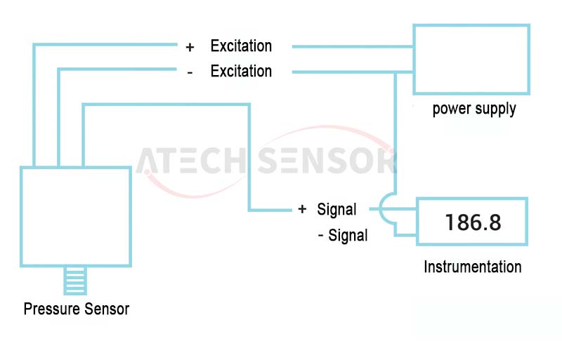
Due to the built-in signal conditioning, the cost is higher and the size is larger than the millivolt output pressure sensor. The amplified voltage signal can be transmitted to moderate distances and is more immune to stray electrical interference than the millivolt signal. The typical wiring configuration for voltage output is shown in the figure below:
3. Current output pressure sensor
Pressure sensors produce millivolt, amplified voltage, or current outputs, and transmitters produce current outputs only.
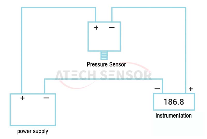
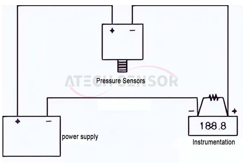
Again, due to the built-in signal conditioning, the transmitter is more expensive and larger in size than a millivolt output sensor. Unlike millivolt and voltage output pressure sensors, the current signal is not affected by any stray electrical interference, which is a valuable asset in the plant. The current signal can also be transmitted over long distances. The typical wiring configuration for a current output pressure sensor is shown in the figure below.
A. Diaphragm - Do not press or touch the diaphragm, as this may damage or alter its calibration, especially on low pressure range models.
B. Fittings and Hardware - Use appropriate pressure rated fittings and hardware, ensuring the correct thread type and size are available. Use pressure limiters, volume chambers, snubbers, etc. if necessary.
C. Operate at Ambient Temperature - Locate the sensor where it can be easily inspected and serviced. The ambient temperature should be within the pressure sensor specifications. The closer the ambient temperature is to 25°C, the less effect the temperature coefficient will have on the overall accuracy of the pressure sensor. Avoid locations subject to excessive vibration.
D. Installation - Installation should only be performed by qualified personnel who are familiar with safety practices and understand all industry recognized standards related to pressure systems. If excessive torque is applied during installation, the sensor calibration and/or zero may shift. Check for zero shift after installation. Refer to standard industry torque data for thread sizes and material types when installing pressure sensors.
One power supply can excite multiple transducers, and the number of transducers that can be used is determined only by the current consumption of each transducer and the current capacity of the power supply.
The sum of the current draw of the pressure sensors cannot exceed the total current capacity of the power supply. For example, if you have 50 pressure sensors that draw 13 mA, you need a power supply with at least 650 mA (50 x 13), or use a power supply with a higher current capacity to power one pressure sensor.
Pressure sensors that output mA signals can be connected in series to multiple devices. They can transmit signals over long distances without interference, so it is easier to connect mA signal devices to multiple instruments.
The following figure illustrates the correct wiring. One of the great advantages of current signaling is the simplicity of setting up a multi-instrument system. Long distance transmission from instrument to instrument, without electrical interference, makes multi-instrument systems easy.
For example, a materials testing center might have one control room for all the different testing laboratories so that they can be operated from one central location.
Instrument calibration and troubleshooting are simple in multi-instrument current loops. The only limitation on the number of instruments is the amount of supply voltage driving the current loop, and the minimum voltage required is determined by Ohm’s law, V-IR (voltage equals current times resistance).
The details are shown in the following figure:
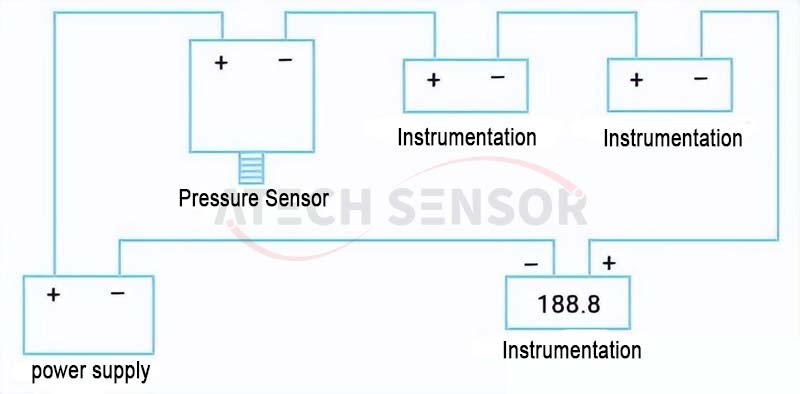
Instrumentation 4-20mA current loop (panel meter, chart recorder, computer, etc.)
It includes: combined instrumentation, pressure sensor, wires, power supply
Assume the following: pressure transmitter (4-20 mA) with a supply voltage of 12-30 Vdc; panel meter with an input impedance of 10 Ω; recorder with an input impedance of 25 Ω; computer with an input impedance of 200 Ω; and lead resistance of 5 Ω.
Then:
Minimum voltage required = (0.020)*(5 + 10 + 25 + 200) + 12 = 16.8 v
24V is the most common power source for 4-20 mA current loops. It is also possible to connect voltage or millivolt signals to multiple instruments, but it is not easy and does not provide the calibration and troubleshooting advantages inherent in current loop systems.
Voltage or millivolt signals can be connected in parallel to multiple instruments as shown in the figure below. This approach assumes that the connected instruments have very high input impedance. If this is not the case, the analog outputs can be used to retransmit the signal.
Multiple instruments connected in parallel to a voltage output pressure sensor
If you are connecting a PX409 mA output pressure sensor to a DP400TP fast response process instrument, you will need to connect all instruments in series. In this case, the DP400TP can also be used as a power supply, providing the 12 V or an additional 20 V DC required to drive the PX409 unit.
Test Systems The PX409 device can be programmed wirelessly using a Near Field Communication (NFC) device such as a mobile phone. The signal from the PX409 can then be fed to a PLATINUM series meter, another type of fast response meter. All PLATINUM meters include a USB output so they can be connected directly to a computer.
After installing the system, you must test it to make sure it is working properly. Follow these three steps:
1. Use a handheld pump to apply pressure to the sensor.
2. Watch to ensure pressure changes across all three units.
3. Verify that once pressure is stable and static, all three units show the same pressure reading.
You can use this procedure to set up a system that will record, log, and graph data from a pressure sensor.
It is a common mistake to try to use multiple sensors, a switchgear, and a panel meter when measuring multiple pressures, even though this saves the cost of multiple panel meters (or any other instrumentation).
The problem is that each sensor has a unique zero point, and there is only one zero screw for the reading. The end result is that the overall accuracy is increased to about 3%, even though each pressure sensor has an accuracy of 0.5%. In most cases, this larger error cannot be tolerated.
1. The correct way to use multiple sensors with one readout device is to use sensors with built-in zero and span adjustment screws, the same output (voltage or current), and the same pressure range.
Each sensor is adjusted by applying a known pressure so that they all have the same output. When they all have the same output, the meter is scaled and the switch can be used.
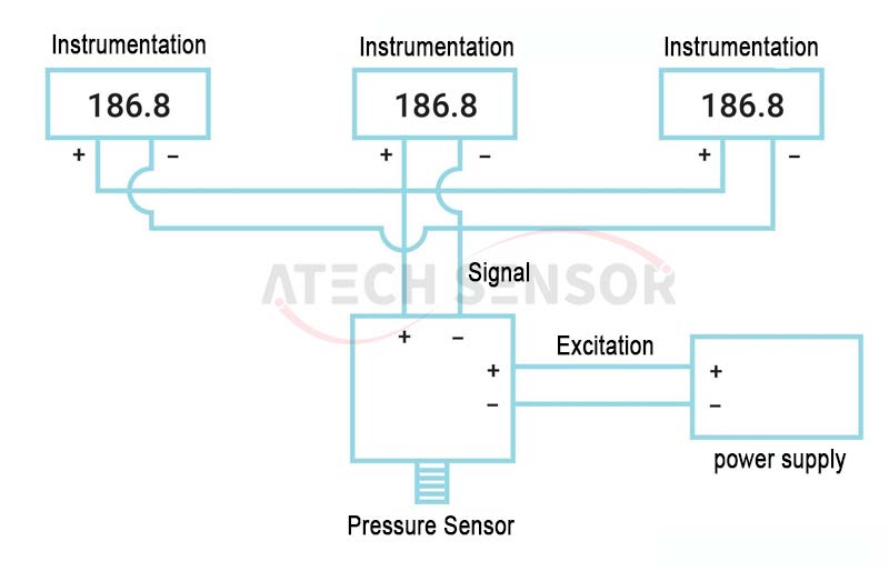
As shown in the picture below: Multiple pressure sensors connected to one meter and one switch (sensors with built-in zero and span adjustments, same output and same pressure range)

2. Another solution to using multiple sensors with one readout is to use scanners instead of meters and switches.
There are many types of scanners, and scanner types that work with multiple pressure sensors must have independent scaling on each channel.
Some scanners offer independent current, voltage, or millivolt inputs for each channel in addition to independent scaling on each channel. These types of scanners enable you to use sensors with different outputs and different pressure ranges on the same instrument.
Most instruments are set up to receive voltage. A common question is how to use an instrument that is set up for current signals and voltage and simply put a resistor across the input terminals of the instrument. The value of the resistor is determined by Ohm's law (V = IR).
For example, installing a 500 ohm resistor will convert 20 mA to 10 V (V = IR = 0.020 x 500).
The details are shown in the following figure:
The only other consideration is zero offset. Since the low side current of most current loops is 4 mA, there will be a zero offset and using the same value resistor as above 4 mA will convert to 2 V.
Convert current to voltage, voltage for meter setting
R=V/I
Where:
R = resistor size
V = desired voltage
I = current
Example: Convert 4-20 mA to 2-10 V
R = V/I = 10/0.02 = 500 Ohms
Then a 500 Ohm resistor would be installed across the (+) and (-) terminals on the meter.
The installation of pressure sensors in pipelines requires professionals who have practical experience in setting up pressure sensors. The reason for choosing professionals is that improper installation can lead to fluid leakage, which can be harmful to both people and machines.
The installation method and positioning of the pressure sensor will depend on the pressure medium (liquid, gas or steam) and the direction of the pipeline. The choice between internal or external pressure sensor installation also depends on the setting.
When choosing a suitable pressure sensor, it is important to pay attention to the following: what pressure sensor needs to be measured, the measurement location and the required output, whether local reading of the pressure reading is necessary, etc., which will be described in more detail below:
Design Issues
What pressure range will the sensor measure under "normal" conditions?
Is gauge, vacuum, compound, sealed, or absolute pressure measurement best suited for this range?
What pressures might the pressure sensor be exposed to under "abnormal" conditions?
How does the pressure sensor connect to the pipes, tanks, lines, and vessels it is measuring pressure?
Will the pressure sensor measure corrosive or chemically aggressive substances?
Environmental Issues
Will the pressure sensor body be exposed to the elements, protected to some degree, or submerged in liquid?
Will the pressure sensor be subjected to strong vibration, shock, or other rough handling?
Output Questions
What electrical output is required or desired from the pressure sensor?
How far away is the nearest/intended power source?
How far does the output signal need to propagate (for control, display, or both)?