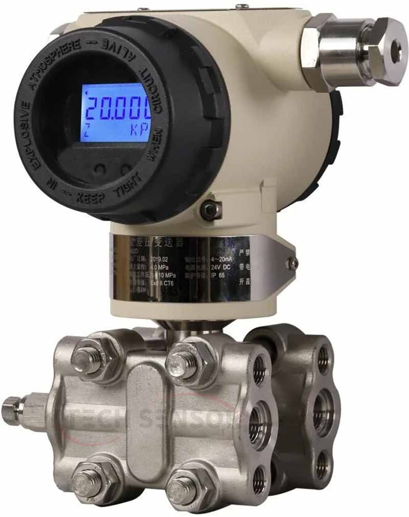
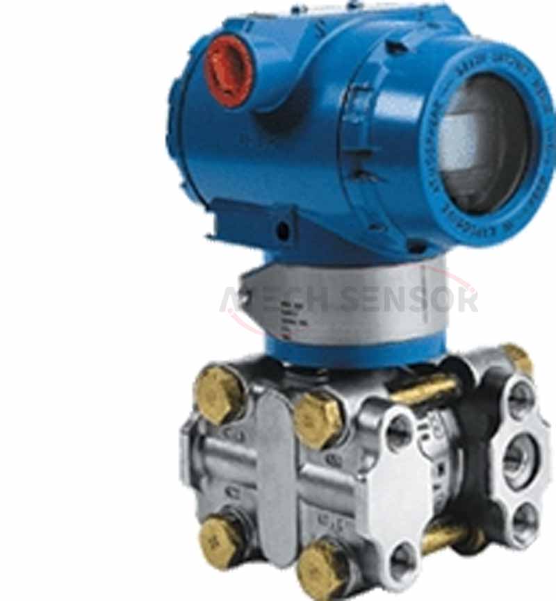
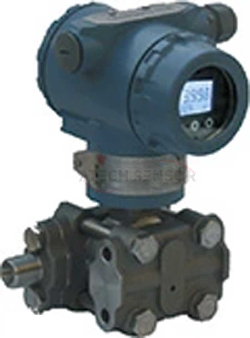
Capacitive pressure transmitter mainly consists of three parts: pressure sensor (also called pressure sensor), measuring circuit and process connection. It can convert the physical pressure parameters of gas, liquid, etc. sensed by the pressure sensor into standard electrical signals (such as 4~20mADC, etc.) to supply secondary instruments such as indicator alarm, recorder, regulator for measurement, indication and process adjustment, and uses 24V power supply.
1.Working principle
The two pressures of the measured medium of the capacitive pressure transmitter are passed into the high and low pressure chambers, acting on the isolation diaphragms on both sides of the delta element (i.e., the sensitive element), and transmitted to both sides of the measuring diaphragm through the isolation diaphragms and the filling liquid in the element. The capacitive pressure transmitter is composed of a capacitor composed of the measuring diaphragm and the electrodes on the insulating sheets on both sides. When the pressures on both sides are inconsistent, the measuring diaphragm is displaced, and the displacement is proportional to the pressure difference, so the capacitance on both sides is not equal. Through the oscillation and demodulation links, it is converted into a signal proportional to the pressure. The working principle of the capacitive pressure transmitter and the capacitive absolute pressure transmitter is the same as that of the differential pressure transmitter, except that the pressure in the low pressure chamber is atmospheric pressure or vacuum. The A/D converter of the capacitive pressure transmitter converts the current of the demodulator into a digital signal, and its value is used by the microprocessor to determine the input pressure value. The microprocessor controls the operation of the transmitter. In addition, it performs sensor linearization. Reset the measurement range. Engineering unit conversion, damping, square root, sensor fine-tuning and other operations, as well as diagnosis and digital communication.
2.Technical Parameters
Analog quantity: two-wire 4~20mADC
Digital quantity: two-wire 4~20mADC and superimposed process variable digital signal in accordance with HART protocol.
Power supply: supply voltage 12.5~45VDC
Load limit: the maximum load resistance Rmax of the loop depends on the supply voltage. HART communication requires the load resistance to be not less than 250Ω and not more than 600Ω
Communication distance: the maximum communication distance is 1.5Km, and multi-station communication can connect up to 15 smart transmitters.
Output display: four-digit digital display, five-digit LCD display, pointer type.
Explosion-proof form: intrinsically safe type: ExiaII CT5; explosion-proof type.
Zero point migration range: The zero point can be migrated positively or negatively at will, but the set upper and lower limits of the measurement range and the range must not exceed the limit value.
Temperature range: Ambient temperature: -40~85℃ (-20~70℃ when LCD indicator is selected)
Measurement medium temperature: -40~104℃
Static pressure and one-way overpressure range: 3.45Kpa (absolute pressure)~31.2MPa (gauge pressure)
Relative humidity: 5~98%RH
Start time: Start within 5 seconds
Capacity change: less than 0.16cm3
Damping adjustment: Time is often 0.20~25 seconds
Fault alarm: If the sensor or circuit fails, the automatic diagnosis function will automatically output 3.9 or 21.0mA
Configuration protection: In order to prevent the configuration data of the transmitter from being arbitrarily changed, the stored data can be locked through software or protection switch.
3. Structural analysis
The pressure transmitter microprocessor has 16 bytes of program RAM and three 16-bit counters, one of which performs A/D conversion.
The D/A converter fine-tunes the data from the corrected digital signal from the microprocessor, which can be modified by the transmitter software. The data is stored in the EEPROM and remains intact even if the power is off.
The digital communication line provides the transmitter with an interface to external devices (such as the 205 intelligent communicator or a control system using the HART protocol). This line detects the digital signal superimposed on the 4-20mA signal and transmits the required information through the loop. The type of communication is frequency shift keying FSK technology and is based on the BeII202 standard.
4. Product Features
●Digital accuracy: + (-) 0.075%
●Stability: 0.075% 60 months
●Range ratio: 100:1
●Measurement rate: 0.2S
●Miniature (2.4kg) all-stainless steel flange, easy to install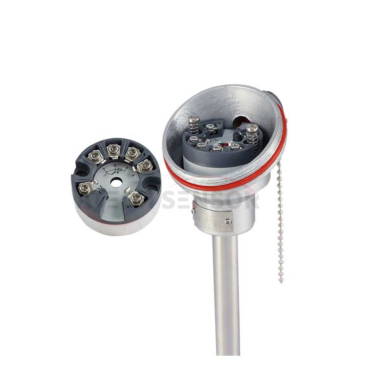
● Process connection is compatible with other products to achieve optimal measurement
● The world's only sensor using H alloy sheath (patented technology), achieving excellent cold and hot stability
● Intelligent transmitter using 16-bit computer
● Standard 4~20m.
● Supports upgrade to fieldbus and field control-based technology
5. Advantages Analysis
Analog characteristics
● High accuracy
● Range and zero point are externally continuously adjustable
● Good stability
● Positive migration can reach 500%, negative migration can reach 600%
● Two-wire system
● Adjustable damping, overpressure resistance
● Solid sensor design
● No mechanical moving parts, less maintenance
● Light weight (2.4kg)
● Unified structure for the entire series, strong interchangeability
● Miniaturization (166mm total height)
● Optional diaphragm material for contact with the medium
● Strong unilateral overpressure resistance
● Low-pressure cast aluminum alloy housing
Intelligent features:
●Superb measurement performance for pressure, differential pressure, liquid level, flow measurement
●Digital accuracy: + (-) 0.05%
●Analog accuracy: + (-) 0.75% + (-) 0.1% F.S
●Full performance: + (-) 0.25 F.S
●Stability: 0.25% 60 months
●Range ratio: 100:1
●Measurement rate: 0.2S
●Miniature (2.4kg) all-stainless steel flange, easy to install
●Process connection compatible with other products for optimal measurement
●The world's only sensor using H alloy sheath (patented technology) to achieve excellent cold and hot stability
●Intelligent transmitter using 16-bit computer
●Standard 4-20mA, with digital signal based on HART protocol, remote control
●Supports upgrades to fieldbus and field control-based technologies.
6. Analysis and processing
The sensitive parts of the capacitive pressure transmitter are all welded, and the electronic circuit is wave soldered and installed with connectors. The overall structure is strong and durable, and there are few failures. For most users, if a sensitive part fails, it is generally impossible to repair it by themselves, and they should contact the manufacturer to replace the entire part.
Inspection of the measuring part of the transmitter
Failures in the measuring part of the transmitter will cause the transmitter to have no output or abnormal output, so the measuring sensitive parts of the transmitter should be checked first.
1) Remove the flange and check whether the isolation diaphragm of the sensitive part is deformed, damaged or leaking.
2) Remove the compensation plate, without removing the sensitive part, and check the insulation resistance of the pin to the shell. When the voltage does not exceed 100V, the insulation resistance should not be less than 100MΩ.
3) Connect the circuit and the gas line. When the pressure signal is at the upper limit of the range, turn off the gas source, and the output voltage and reading value should be stable. If the output voltage drops, it means that the transmitter is leaking, and the leaking part can be checked with soapy water.
Inspection of the transmitter circuit
1) Turn on the power and check the status of the voltage signal at the output end of the transmitter. If there is no output voltage, first check whether the power supply voltage is normal; whether it meets the power supply requirements; whether there is any wiring error between the power supply and the transmitter and the load device. If there is no voltage on the transmitter terminal or the polarity is reversed, the transmitter will have no voltage signal output. Excluding the above reasons, further check whether the components in the amplifier board circuit are damaged; whether the circuit board connectors have poor contact. The method of comparing the measured voltage of the normal instrument with the measured voltage corresponding to the faulty instrument can be used to determine the fault point. If necessary, the faulty amplifier board can be replaced. When checking the flow transmitter, special attention should be paid to anti-static measures for the J-type amplifier board.
2) Turn on the power. After the input pressure signal is given, if the transmitter output is too high (greater than 10VDC), or the output is too low (less than 2.0VDC), and the output does not respond when the input pressure signal is changed and the zero point and range screws are adjusted. For this type of fault, in addition to checking whether there are any abnormalities in the sensitive parts of the transmitter measurement part, the "oscillation control circuit part" on the transmitter amplifier board should be checked to see if it is working properly. The normal peak voltage between the high-frequency transformer T1-12 should be 25~35VP-P; the frequency is about 32kHz. Secondly, check the working conditions of each operational amplifier on the amplifier board; whether the components of each part are damaged, etc. This type of fault requires the replacement of the amplifier board.
3) The transmitter has very strict requirements on the circuit design and process assembly quality. In actual use, for the circuit fault that occurs, it is best to contact the manufacturer to replace the faulty circuit board after inspection and confirmation to ensure the long-term stability and reliability of the instrument.
On-site fault inspection
Most of the faults that occur at the construction site are caused by improper use and installation methods, which can be summarized in several aspects.
1) The primary element (orifice plate, remote measurement joint, etc.) is blocked or the installation form is incorrect, and the pressure point is unreasonable.
2) The pressure pipe leaks or is blocked, there is residual gas in the filling pipe or residual liquid in the filling pipe, and there are sediments in the transmitter process flange, forming a measurement dead zone.
3) The transmitter wiring is incorrect, the power supply voltage is too high or too low, and the connection between the indicator head and the instrument terminal is poor.
4) The installation is not strictly in accordance with the technical requirements, and the installation method and on-site environment do not meet the technical requirements.
The above faults will cause abnormal transmitter output or inaccurate measurement, but after careful inspection, strict use and installation in accordance with the technical requirements, and timely and effective measures, the problems can be eliminated. For faults that cannot be handled, the transmitter should be sent to the laboratory or manufacturer for further inspection.