1. Overview
This instrument contains a number of patented technologies and has the characteristics of safety, cleanliness, high precision, long life, stability and reliability, easy installation and maintenance, etc. It is suitable for various fields such as acid, alkali, salt, corrosion resistance, and high temperature.
This instrument can be connected to the display meter or various DCS systems via 4~20mA to provide real-time liquid level data for industrial automation operation.
This instrument has the following features:
●The circuit design uses high-quality power modules from the power supply part, and the components are imported high-stability and reliable devices, which can completely replace the same type of foreign imported instruments.
●The patented acoustic wave intelligent technology software can perform intelligent echo analysis without any debugging and other special steps. This technology has the functions of dynamic thinking and dynamic analysis.
●The patented acoustic wave intelligent technology owned by our company greatly improves the accuracy of the instrument, and the liquid level accuracy reaches ±0.25%, which can resist various interference waves.
●This instrument is a non-contact instrument that does not come into direct contact with the liquid, so the failure rate is low. The instrument provides a variety of installation methods, and users can calibrate the instrument through this manual.
●All input and output lines of the instrument have lightning protection and short-circuit protection functions.
2. Technical indicators
Measuring range: 0~5M 0~10M 0~15M ....
Blind area: 0.45m~0.6m
Distance accuracy: ±0.25-5% (standard conditions)
Distance resolution: 1mm
Pressure: Normal pressure
Instrument display: Built-in LCD display
Analog output: 4~20mA
Power supply voltage: DC24V
Ambient temperature: -20℃ ~ +60℃
Protection level: IP65
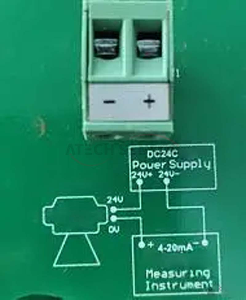
3. Instrument wiring
4. Meaning of installation parameters
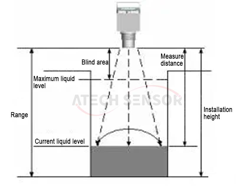
As shown in the figure above, the instrument probe sends waves that hit the liquid level and then reflect back to the probe. After receiving the waves, the probe calculates the time from sending the waves to receiving the waves to obtain the measured distance L. The current liquid level H can be obtained by subtracting the measured distance L from the instrument installation height TH.
The instrument range refers to the distance that the instrument can measure, and the installation height TH should be smaller than the range.
The blind area of the instrument refers to the area near the probe that the instrument cannot measure. The distance between the highest liquid level and the probe should be greater than the blind area. For example, if the blind area is 0.5m, the distance between the highest liquid level and the probe must be greater than 0.5m. For example: range: 6 meters, blind area: 0.45 meters, actual measurement: 0~5.55 meters
The wave emission of the probe is a diffusion process, that is, it has a directional angle. Please pay attention when installing it, otherwise it may hit the protrusions on the pool wall or the edge of the channel.
5. Instrument installation principles
A1) The distance from the probe emission surface to the lowest liquid level should be less than the range of the instrument.
A2) The distance from the probe emission surface to the highest liquid level should be greater than the blind area of the instrument.
A3) The emission surface of the probe should be parallel to the liquid surface.
A4) The installation position of the probe should try to avoid the position where the liquid level fluctuates violently, such as the inlet and outlet directly below.
A5) If the pool wall or tank wall is not smooth, the instrument installation position needs to be more than 0.5m away from the pool wall or tank wall.
A6) If the distance from the probe emission surface to the highest liquid level is less than the blind area of the instrument, an extension tube needs to be installed. The extension tube diameter is greater than 120mm, the length is 0.45m~0.60m, and it is installed vertically. The inner wall is smooth, and the opening on the tank should be larger than the inner diameter of the extension tube. Or pass the tube to the bottom of the tank, the diameter is greater than 120mm, and a hole is left at the bottom of the tube to keep the liquid level in the extension tube at the same height as in the tank.
6. Installation precautions
1) When installing the instrument outdoors, it is recommended to install a sunshade to extend the service life of the instrument.
2) The wire and cable protection tubes should be sealed to prevent water accumulation.
3) Although the meter itself has a lightning protection device, when the meter is used in areas with frequent lightning strikes, it is recommended to install a special lightning protection device at the inlet and outlet ends of the meter.
4) When the instrument is used in particularly hot or cold places, that is, when the ambient temperature may exceed the working requirements of the instrument, it is recommended to add high and low temperature protection devices around the liquid level meter.
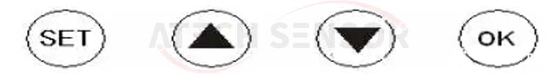
7. Keyboard Description
8. Parameter setting <Only P06 and P02 need to be set, other menus do not need to be set. If you need to set, please contact the manufacturer, otherwise the data will be messed up and cause abnormal data.
P02 (20mA setting)
When the meter is working normally, press SET for about 3 seconds, 0000 will appear, and the first 0 will flash. Change the first 0 to 1, and then press OK to enter the menu. Press the ▼ key to select P02, which is the liquid level corresponding to 20mA. If you need to modify it, press the OK key first, then press ▲ and ▼ to modify it. After the modification is completed, press SET to exit. Press the ▼ key, P03 will appear. P03 is the 4mA output current setting. The default value is 0, and generally no modification is required. If you need to modify it, the method is the same as modifying 20mA.
P06 (Probe height setting) The installation height refers to the distance from the probe to the bottom of the pool or tank
The P06 menu is the probe height, that is, the distance from the probe surface to the bottom of the pool, also called the installation height, which can be used for calibration. If the current liquid level is unknown on site, the P06 menu can be used for liquid level calibration. If you need to modify it, the method is the same as above.
9. Warranty Policy
Users are requested to present the warranty card during repair. During the warranty period, if a fault occurs due to normal use, you can enjoy the prescribed free warranty with the warranty card.
Warranty period: The warranty period of our company's products is twelve months from the date of acceptance.
The following situations are not covered by the free warranty:
●The product or its parts have exceeded the free warranty period.
●Hardware failure caused by the use environment not meeting the product use requirements.
●Failure or damage caused by poor power supply environment or foreign matter entering the device.
●Failure caused by failure to operate according to the instructions and precautions written in the operation manual.
●Failure caused by force majeure such as natural factors such as lightning, water and fire.
●Failure or damage caused by unauthorized disassembly and repair, unauthorized modification or abuse.